D33 meter
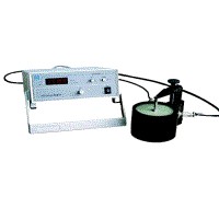
D33 Test Meter

1. DESCRIPTION
The Model YE2730 d33 meter is a special instrument directly to measure piezoelectric constant d33 values of piezoelectric ceramics, polymers, and single crystals. This meter can also measure d33 value in various single crystal materials, such as lithium niobate, quartz, and tourmaline. This meter is capable of measuring d33 value over a very large range, at high resolution, and with a high degree of reliability. The measurement is quickly, and easily made with a minimum of training required. Specimens of a variety of sizes and shapes can easily be accommodated and measured. For example: d33 value of disks, blocks, rings, tubes and semispherical shells can be easily measured and displayed on the Model YE2730 d33 meter. Measuring d33 value is displayed on a 3 1/2 inch digital meter. This instrument is invaluable as a tool for quality assurance of piezoelectric materials, production in-line inspection, or for research applications.
2. SPECIFICATIONS
D33 Range: x 1 range: 10 to 2000 PC/N
x 0.1 range: 1 to 200 PC/N
Accuracy: x 1 range: ±2% of d33 value in 100 to 2000 PC/N
±5% of d33 value in 10 to 200 PC/N
x 0.1 range:.±2% of d33 value in 10 to 200 PC/N
±5% of d33 value in 1 to 20 PC/N
Resolution:. x 1 range: 1 PC/N
. x 0.1 range: 0.1 PC/N
Force: Frequency: 110Hz Amplitude: 0.25N
Polarity Indication: indicates polarity on upper face of test element in compression. (“-“sign means negative, no sign positive)
Shunt Capacitance: 1 pF (for x 1 range)
0.1 pF (for x 0.1 range)
Dimensions: .Force Head: 110x140mm, Chassis: 280x200x90mm
Weight: Force Head: 3 kgs, Chassis: 2 kgs
Power: 110/220V, 50/60Hz, 20W (In the instrument panel on the back of the switch are switch selectable.)

3. FRONT PANEL OVERVIEW
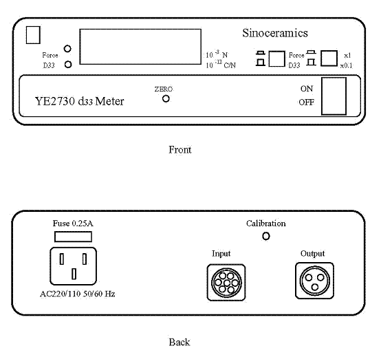
3.1 D33 Range Key: to choose x1 or x0.1. Pushing down (x 1), measuring range is from 10 to 2000 PC/N, resolution is 1PC/N for normal piezo material such as piezo ceramics. Pushing up (x0.1), measuring range is from 1 to 200 PC/N, resolution is 0.1 PC/N for low piezoelectric constant material such as piezo crystal.
3.2 Force and d33 Key: Pushing down force light on. Digital display shows force exerted on the sample by shaker at (250±10) x 10-3 N. If force is too high or too low (> 250±20) x 10-3 N, you have to turn shaker’s knob to adjust clamping force on the test sample.
3.3 31/2 digital display shows force exerted on the test sample or d33 value of test sample. The display indicates polarity on upper face of test element in compression. ( “-“ sign means negative, no sign positive )
3.4 Power switch turn on the display and display light of force or d33 will turn on.
3.5 Zero adjust knob: adjust the knob to get system balance for high accuracy measurement result. (see calibration)
4. BACK PANEL OVERVIEW
4.1 Output plug: Three pins plug is connected with shaker to supply the power, let shaker output 110 Hz frequency and 0.25 N force.
4.2 Input plug: Eight pins plug is connected with shaker to pick up the signal from shaker.
4.3 AC power plug: AC 60/50 Hz, 110/220 Volt AC plug with 0.5A fuse for 110V AC power, 0.25A fuse for 220V AC power supply. Before plug in AC power, please check local AC power voltage in order to set up AC voltage into the meter.

5. SHARKER OVERVIEW
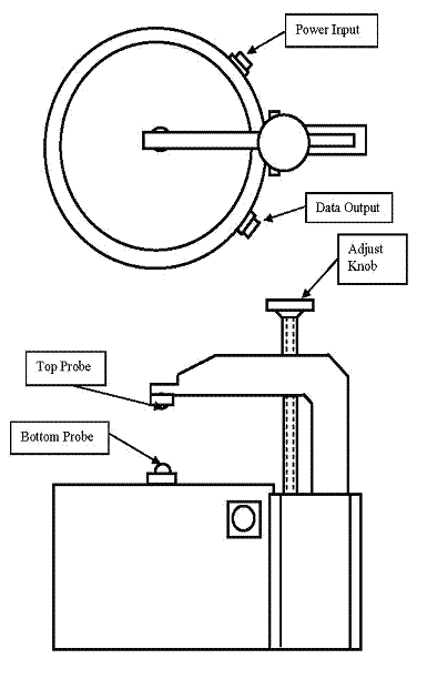
5.1 Adjust knob: Turn adjusting knob to drive top probe up or down. Test sample will be clamped between top probe and bottom probe. Do not screw the sample too tight.
5.2 Top and Bottom probe transfer signal from test sample to measuring system, and hold the sample driving the sample vibration.
5.3 Output and Input connector: Three pins input plug is connected with the meter to supply the power to shaker. Eight pins output plug is connected with the meter to send the signal to the meter.
6. SETUP AND CALIBRATION
6.1 Connecting the meter input and output plug with shaker output and input plug respectively by the two coaxial cables supplied with the system.
6.2 Turn on the meter for 15 minutes, put standard test sample between top and bottom probes.
6.3 Turn Force and d33 switch to Force. The meter readout should be (250±10)x10-3 N. If not, adjust the probe’s knob. and keep Force readout fixed at (250±10) x 10-3 N.
6.4 Turn Force and d33 switch to d33. The meter readout should be close to d33 value of standard test sample. Write down the value of meter displayed for D1. Then turn standard test sample 180° and measure the sample again. The meter will show opposite polarization and d33 value for D2. If two values D1 and D2 are different, to calculate D3 by (D1 + D2) x 0.5, then use Zero point to adjust knob to get D3 value. Now test sample negative and positive values should be the same.
6.5 Adjust back panel calibration screw, let the meter display the same value as standard test sample marked.
6.6 The manufacturer has already calibrated the meter before shipping out. But we do suggest you to make a calibration for every month at least.
7. OPERATION
7.1 Put test sample between two probes and keep the clamps to be close the sample center as possible. Turn adjust knob of top probe lightly to clamp test sample. Don’t clamp the sample too tight until measuring readout is displayed stably. If clamping too tight or too loose, it will cause test results inaccurate.
7.2 If you want to measure the same thickness one, you just lightly push down bottom probe to change test sample. Don’t need to adjust the knob any more.
7.3 Two different shape probes are supplied with the meter for measurement. We recommend to use the corn shape probe to measure most of test samples. For measuring big parts with very flat, one of flat probes can be put on the bottom side.
7.4 When testing large capacitance sample, measurement value should make a modification. If not, accuracy will be over 1%. Following equation will be used to calculate the true value.
d33 (modified)= d33(Display) x ( 1+Cc ) For switch on " x1 "
d33 (modified)= d33(Display) x ( 1+10Cc ) For switch on " x0.1 "
Cc = capacitor of sample ( μF )
8. CALCULATE ε33 AND g33
Relative dielectric coefficient ε33= (TxC)÷(ε0 x S)
T = thickness of test sample (m)
S = area of sample electrode (m2)
C= capacitance of test sample (F)
ε0= 8.85 x 10⁻¹² F/m
Piezo voltage constant g33 = d33÷ε33
9. MAINTENANCE
This system is maintenance free. If you find any trouble, please send it back to local dealer or us for reparation.
Please read operation manual carefully before using the meter.
Thank you for interesting in our d33 meter.
10. ACCESSOIES
Three-core cable with connectors .1 piece
Seven-core cable with connectors 1 piece
Power cord 1 piece
Corn shape Probe 2 pieces
Plate shape probe 2 pieces
Standard test sample .1 piece
Fuse 1 piece
Operating manual .1 piece
Tel: +86-21-64384700 email: info@sinocera.net

